Almost every Jeep on the trail has some kind of after market accessory that requires power. Each lightbar, axle locker and compressor requires a switch and running all these wires into the cabin can create a real rat’s nest under the hood and behind the dash.
There are aftermarket solutions such as the SPOD and the new JL offers 4 programmable buttons to control accessories. The SPOD is quite expensive, and we can’t all upgrade to the JL, so here’s how you can clean up your wiring and build your own Accessory Control Module (ACM).
The Basics
Many of those accessories come with wiring harnesses, which work great if you’re wiring one accessory, but when you’ve got 4 or 5 of them coming into your dash, it becomes a mess and they usually have the following components.
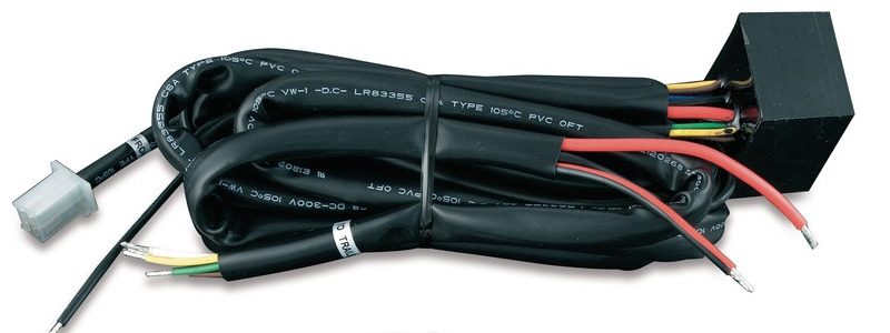
- A fuse – generally there’s an in-line fuse to protect your vehicle in case of a short circuit. There may be two fuses, one for the accessory power, one for he switch power).
- A relay – the relay is an electronic switch. When the coil in the relay is powered, it flips the internal switch to provide power to the accessory.
- A switch – provides power to the relay coil activating it and the accessory.
- Wires – In addition to the wires running to the lightbar or whatever, there are usually three or four other connections:
- Accessory Power – powers the actual thing you’re trying to control
- Switch Power – provides power to the switch and eventually the relay coil.
- Ground – completes the circuit by connecting to chassis ground. There may be two ground connections, one for the switch (so the little light can come on) and one for the relay coil and the accessory.
I could explain how all these components are wired together, but this is well documented in every accessory’s installation manual and a quick Google search will yield hundreds of results showing the same basic diagram.
Parts List
Since we’re basically recreating the wiring harness described above, but for multiple accessories, the parts list will appear to be very similar and can be scaled up or down based on your needs.
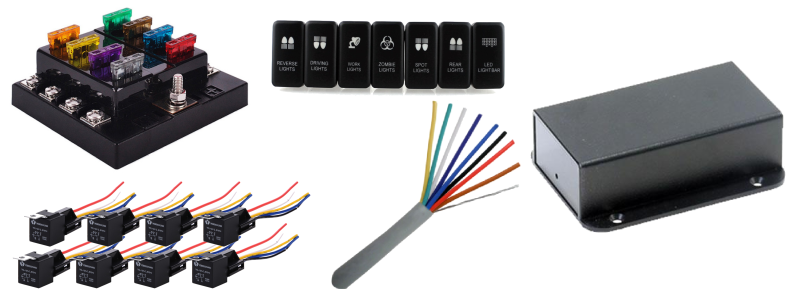
- Common-feed fuse panel – This will be the power source for all your accessories and are available in different sizes
- 30A automotive relays with harnesses – These will control your accessories.
- Switches – You can buy individual switches, or buy a switch panel, whatever suits you.
- Multi-conductor wire – These will run power from the switches inside the cabin to the relays under the hood. It is essential that the wires be in different colors so you can tell them apart.
- High gauge wire – 4 gauge is recommended for this.
- Project box – This part is optional, but putting the relays and perhaps the fuse panel into a project box makes for a clean installation.
Wiring
The wiring for this project is not that complex, but does take a little time with work under the hood and in the cabin.
Under the Hood
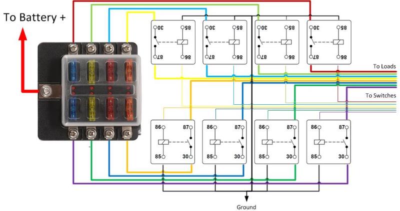
- Using a high gauge wire connect the input of the fuse panel to the battery. You can buy a pre-fabricated cable with eyelets at each end for connection to the battery and fuse panel. The closer to the battery you install the fuse panel, the better.
- From each fuse output, run a wire to the input terminal of the relay. On most automotive relays, this terminal will be labeled 30.
- Connect thee relay output labeled 87 to each load (light bar, locker, etc.).
- Connect the ground terminal (labeled 85) from each relay to the chassis.
- Connect the relay control terminal (labeled 86) from each relay to one of the wires in your multi-conductor cable for connection with the switches.
This is the basic wiring required. You can choose to put all of these components into an enclosure for a nice clean install, and use a terminal block between the relays and the loads for easier connection. You can also choose to use an aircraft or marine grade connector for the multi-conductor cable feeding into the cabin.
Make sure you populate the fuse panel with a fuse appropriate for the load. If your lightbar draws 8 amps, use a 10A fuse, but if your compressor draws 30A, use a 30A fuse. You can usually figure out what fuse size to use based on the fuse that came with the standard wiring harness or by reading the specifications.
In the Cabin
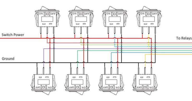
- Connect each of the colored wires from the relays to one of the switches. Make sure the switch you want to use for each accessory is connected to the correct relay under the hood. On most illuminated switches, this will be the middle terminal.
- Connect each of the switches to ground. This is usually the terminal on the Off side of the switch.
- Connect each switch to power. This is usually the terminal on the On side of the switch.
Depending on the accessory, and how you want it to operate, you may choose to source power from different sources and you can use different sources based on how you want that accessory to work. For example, if you want to use your lightbar even when the vehicle isn’t running, you would source constant power either directly from the battery, or a lighter jack that is always on. If you want your lockers to disengage when you turn the vehicle off (not much point in leavng them on), then you could source power from a switched source such as a lighter plug that turns off with the vehicle.
The switches only activate the relays and the current draw for the relays is minimal (less than 200mA per relay), so you aren’t likely to overload a circuit by tapping it to provide power to the switches. You could use an add-a-fuse, however, if you prefer to add a circuit of your own, which is a warranty friendly way to do this.
How it Works
The operation is pretty straight forward. When you a switch inside the vehicle, the switch supplies power to the relay coil. The coil causes the relay to switch allowing power to flow from the new fuse panel to the load (lightbar, locker, etc).
The overall installation should provide an easier way to install and troubleshoot your accessories and clean up the wiring under your hood and behind your dash.